Nanotechnology
We developed specialized instrumentation to help researchers and companies in fundamental research, develop new products/applications, and QA/QC. We are currently developing methods to improve the agglomeration behavior of nanoparticles and their filtration from process gases. We also provide specialized services such as performing safety assessment, technology feasibility assessment, and process design.
- Software
- Dust Explosion
- Fractal Analysis of Agglomerate Structure
- Instrumentation
- Case Studies
Size Distribution of Spherical Particles
In the first test, 240 nm spherical latex particles were used and five different samples of increasing number concentrations were tested. In the second test, 80 and 100 nm latex spheres were tested. Experimentally measured extinction spectra for 240 nm (different particle concentrations) and 100 and 80 nm are shown in Figure 1 and Figure 2 below. The size distribution obtained by inverting the extinction data using our proprietary code based on a modified Chahine iteration algorithm are also included in the figures. It is observed from the figures that the results are in good agreement with the sizes of latex particles used. Results from our inversion algorithm are highly reproducible. A remarkable achievement here is that this technique can provide accurate size even when the particle size is smaller than the wavelength, a region where existing commercial static light scattering instruments fail. Our technique is continuously improved to meet evolving industry needs.
The small peak seen next to the larger peak in Figure 1 is a numerical artifact at low particle concentrations. The peak disappears at high particle concentrations. A possible solution to overcome this error is to run measurements at different particle loadings. We are also refining our numerical simulations to overcome this problem.
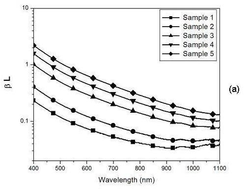
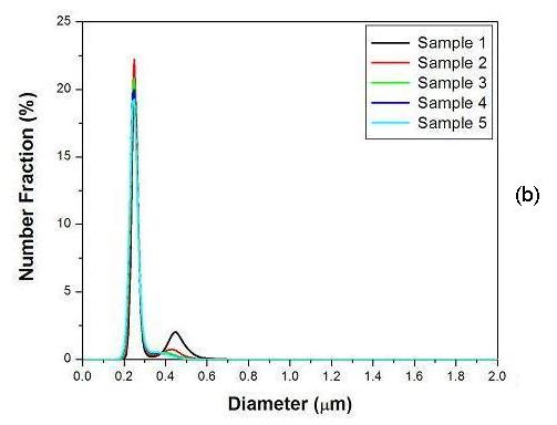
Figure 1(a-b) - Experimental data and size after inversion for 240 nm latex particles
Even though the particles used in the measurements were monodispersed, the results in Figure 2 show a slight spread in the distribution. This is because the spectrometer used was not designed for this purpose and there are variations of beam shape with wavelength. The beam was not circular but changes its shape during propagation before reaching the detector. As the particle size decreases the data spread increases i.e., these issues become important in determining the instrument accuracy for this application. We are currently building a spectrometer with a well-defined beam size and shape specifically for particle sizing to overcome this problem.
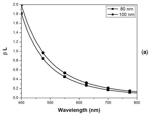
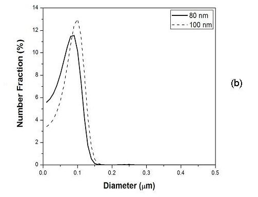
Figure 2(a-b) - Experimental data and size after inversion for 80 and 100 nm particles
Size and Aspect Ratio Distribution of Ellipsoidal Particles
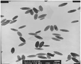
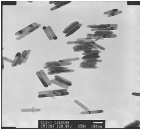
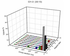
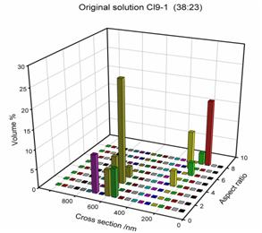
We performed polarized light scattering measurements on Haematite nanoparticles synthesized by Herbert Giesche from NYSCC at Alfred University, NY by aging aqueous FeCl3 or Fe(NO3)3 solutions at 100°C. Samples were extracted at various times during their synthesis and were suspended in water for our measurements. We inverted the polarized light scattering data collected at various scattering angles and polarization states using our proprietary inversion algorithms to determine the cross sectional diameter and aspect ratio distribution of the suspension. Also, electron microscopy was performed to compare our results. The Electron Microscopy pictures and the results obtained with our instrument are compared in the figures below. The sample extracted at 33:13 minutes had cross sectional diameters between 50 and 200 nm and aspect ratios between 1 and 2. The sample extracted at 38:23 minutes had cross-sectional diameters between 550 and 700 nm and aspect ratios of 1 â�� 4 mainly. The increase in both the diameter and the aspect ratio between the two sampling times could be due to the growth of particles. There were some particles which had cross-sectional diameters between 150 and 250 nm and aspect ratios between 4 and 8. These could be either due to growth or end-to-end agglomeration. The close agreement between our measurements and the SEM pictures validates our measurement technique for the morphology characterization of non-spherical particles.
Fractal Analysis of Agglomerates and Carbon Nanotubes
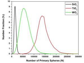
We performed morphology characterization of silicon oxide, titanium dioxide and tungsten oxide nanoparticles suspended in water. All these particles tend to agglomerate. Using polarized light extinction spectroscopy, we measured the number distribution of primary particles per agglomerate and these results are plotted in the figure below
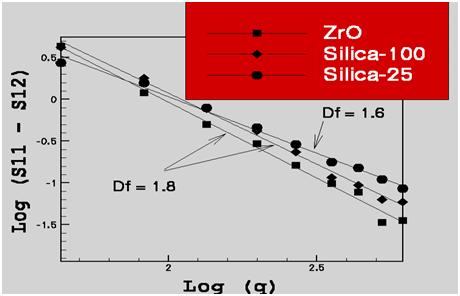
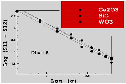
Also, we performed polarized light scattering measurements on the following ceramic nanoparticle samples: silica suspended in water (silica-100 in the figure below), silica suspended in 25% isopropanol and 75% water (silica-25), zirconium oxide suspended in water (ZrO) , cerium oxide suspended in water (Ce2O3), silicon carbide suspended in water (SiC) and tungsten oxide suspended in water (WO3). We calculated the scattering matrix elements from the angular scattering data at various polarization states and plotted log (S11-S12) versus log(q) where q is a function of scattering angle. The slope of these curves is the fractal dimension. The results below show that changing the solvent from water to isopropanol-water solution does not affect the fractal dimension of silica nanoparticles. We obtained fractal dimensions between 1.6 and 1.8 for these suspensions.
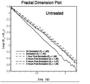
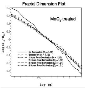
We performed polarized light extinction measurements on two types of carbon nanotubes suspended in water: (1) untreated CNTs and (2) CNTs treated with molybdenum oxide (MoO3). For each sample, we performed extinction measurements on the raw sample as well as sample sonicated for various times. Plots for log(S11-S12) versus log(q) data for the various samples and sonication times are plotted in the figure below. Comparison of these results shows that: Sonication leads to a reduction in fractal dimension for both untreated and MoO3 treated samples because the CNTs become dis-entangled and more chain-like during sonication. MoO3 treatment causes the CNTs to become less compact and as a result the fractal dimension is slightly lower for the treated sample.
Characterization of Coated (Core/Shell) Particles Using Polarized Extinction Spectroscopy
We performed numerical simulations to demonstrate the feasibility of our approach to characterize coated particles (experimental measurements are currently underway). A numerically simulation was performed, using Lorenz-Mie theory for coated spheres, to obtain extinction spectrum. The following input were used in the simulations:
- Overall size of the particles: 200 nm
- Coating thickness variation: 2 to 20 nm (a log-normal distribution with mean of 10 nm and standard deviation of 1.25). Note that this is not the variation within each particle, but across the whole population of particles. We assumed a uniform coating thickness for each individual particle.
- Refractive index of the core: 1.36 + 0.0i
- Refractive index of the coating: 1.48 + 0.5i
To represent experimental conditions, three different turbidity spectral data sets were created with +/- 2%, +/- 5%, and +/- 10% maximum value random noise added to the simulated spectra (the actual noise in the experiments would be less than 1%). The simulated spectrums with and without noise (+/- 10%) are shown in Figure 1 as case B and A, respectively.
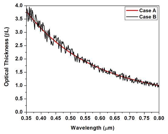
Figure 1 - Numerically Simulated Extinction Data with Noise
Inversion was performed to obtain the distribution of coating thickness values by using modified Chahine iteration scheme. The results are depicted in Figure 2. Although we obtained results for different random noise values, we present only the case in which recovered distribution considerably deviated from the distribution used for simulation. The symbols in the figure represent the values used as input to simulate the turbidity spectra. Case B and A, respectively, represent the inversion performed with simulated spectrum with and without noise added to it From the results, it is evident that it is possible to obtain coating thickness variations in a particle suspension containing monodispersed particles (with reasonable accuracy.)
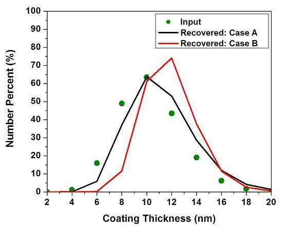
Figure 2 - Coating thickness distribution after inversion
